

Wireless Network in Computer Networking System, study of computer network system, study of computer for students, topic read computer related online.
IEEE 802.11 : Wireless LAN – wireless network
Architecture: The 802.11 architecture defines types of wines and Affi types of stations.
Services: The two types of services are
1. Basic services set (BSS)
2 Extended Service Set (ESS)
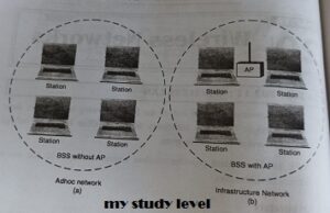
Basic Services Set (BSS)
The basic services set contains stationary or mobile wireless stations and central base station called access point (AP).
The use of access point is optional.
If the access point is not present in ko sand-alone network. Such a BSS cannot send data to other BSS. This type of architecture is kn adhoc architecture.
The BSS in which an access point is present is known as infrastructure network.
wireless network topic on my study level
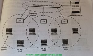
2. Extended Service Set (ESS) – wireless network
An extended service set is created by joining two or more basic services sets (BSS) having access points (APs) as shown in fig. 20.2
These extended networks are created by joining the access points of basic services sets through a wired LAN known as distribution system.
The distribution system can be any IEEE LAN.
There are two types of stations in ESS:
(i) Mobile stations: These are normal stations inside a BSS.
(ii) Stationary stations: These are AP stations that are part of a wired LAN Communication between two stations in two different BSS usually occurs via
A mobile station can belong to more than one BSS at the same time.
extended service set on mystudylevel
Station Types
IEEE 802.11 defines three types of stations on the basis of their mobility in wireless
LAN. These are:
1. No-transition Mobility
2. BSS-transition Mobility
3. ESS-transition Mobility
1. No-transition Mobility: These types of stations are either stationary Le. immovable or move only inside a BSS.
2. BSS-transition mobility: These type of stations can move from one BSS to another but the movement is limited inside an ESS.
3. ESS-transition mobility: These type of stations can move from one ESS to another. The communication may or may not be continuous when a station moves from one ESS to another ESS.
Physical layer functions
As we know that physical layer is responsible for converting data stream into signals, the bits of 802.11 network can be converted to radiowaves or infrared waves.
These are six different specifications of IEEE 802.11. These implementations, except the first one, operates in industrial, scientific and medical (ISM) band. These three banks are unlicensed and their ranges are
1. 902-928 MHz
2. 2.400-4.835 GHz
3. 5.725-5.850 GHz
The different implementations of IEE802.11 are given below:-
1. IEEE 802.11 infrared
It uses diffused (not line of sight) infrared light in the range of 800 to 950 nm.
. It allows two different speeds: 1 Mbps and 2Mbps.
For a 1-Mbps data rate, 4 bits of data are encoded into 16 bit code. This 16 bit
code contains fifteen Os and a single 1.
For a 2-Mbps data rate, a 2 bit code is encoded into 4 bit code. This 4 bit
code contains three Os and a single 1. The modulation technique used is pulse position modulation (PPM) Le for
converting digital signal to analog.
2. IEEE 802.11 FHSS
. IEEE 802.11 uses Frequency Hoping Spread Spectrum (FHSS) method for signal generation.
.This method uses 2.4 GHz ISM band. This band is divided into 79 subbands of IMHz with some guard bands.
In this method, at one moment data is sent by using one carrier frequency and then by some other carrier frequency at next moment. After this, an idle time is there in communication. This cycle is repeated after regular intervals.
A pseudo random number generator selects the hopping sequence. The allowed data rates are 1 or 2 Mbps.
. This method uses frequency shift keying (two level or four level) for modulation i.e. for converting digital signal to analogy.
3. IEEE 802.11 DSSS – wireless network
This method uses Direct Sequence Spread Spectrum (DSSS) method for signal generation. Each bit is transmitted as 11 chips using a Barker sequence.
DSSS uses the 2.4-GHz ISM band. It also allows the data rates of 1 or 2 Mbps.
It uses phase shift keying (PSK) technique at 1 Mbaud for converting digital
signal to analog signal.
4. IEEE 802.11a OFDM
This method uses Orthorgonal Frequency Division Multiplexing (OFDM) for signal generation.
This method is capable of delivering data upto 18 or 54 Mbps. In OFDM all the subbands are used by one source at a given time.
It uses 5 GHz ISM band. This band is divided into 52 subbands, with 48 subbands for data and 4 subbands for control information.
If phase shift keying (PSK) is used for modulation then data rate is 18 Mbps. If quadrature amplitude modulation (QAM) is used, the data rate can be 54 Mbps.
5. IEEE 802.11b HR-OSSS — wireless network
. It uses High Rate Direct Sequence Spread Spectrum method for signal generation. HR-DSSS is similar to DSSS except for encoding method.
Here, 4 or 8 bits are encoded into a special symbol called complementary code key (CCK).
It uses 2.4 GHz ISM band.
• It supports four data rates: 1, 2, 5.5 and 11 Mbps.
⚫ 1 Mbps and 2 Mbps data rates uses phase shift modulation.
• The 5.5. Mbps version uses BPSK and transmits at 1.375 Mbaud’s with 4-bit CCK encoding. The 11 Mbps version uses QPSK and transmits at 1.375 Mbps with 8-bit CCK encoding.
6. IEEE 802.11g OFDM
It uses OFDM modulation technique.
⚫It uses 2.4 GHz ISM band.
⚫ It supports the data rates of 22 or 54 Mbps. 802.11b.
⚫ It is backward compatible with 20.1.3
MAC sublayer Functions – wireless network
⚫ 802.11 supports two different modes of operations. These are:
1. Distributed Coordination Function (DCF)
2. Point Coordination Function (PCF)
1. Distributed Coordination Function
⚫ The DCF is used in BSS having no access point.
⚫ DCF uses CSMA/CA protocol for transmission. ⚫ The following steps are followed in this method (see figure 20.4):
1. When a station wants to transmit, it senses the channel to see whether it is free or not.
2. If the channel is not free the station waits for backoff time.”
3. If the station finds a channel to be idle, the station waits for a period of
time called distributed interframe space (DIFS). 4. The station then sends control frame called request to send (RTS) as shown in figure 20.4.1
5. The destination station receives the frame and waits for a short period of time called short interframe space (SIFS).
6. The destination station then sends a control frame called clear to send (CTS) to the source station. This frame indicates that the destination station is ready to receive data.
7. The sendor then waits for SIFS time and sends data.
8. The destination waits for SIFS time and sends acknowledgement for the received frame.

ieee figure my study level
Collision avoidance — wireless network
802.11 standard uses Network Allocation Vector (NAV) for collision avoidance.
The procedure used in NAV is explained below:
1. Whenever a station sends an RTS frame, it includes the duration of time for which the station will occupy the channel.
2. All other stations that are affected by the transmission creates a timer called network allocation vector (NAV).
3. This NAV (created by other stations) specifies for how much not time these stations must check the channel.
4. Each station before sensing the channel, check its NAV to see if h expired or not.
5. If its NAV has expired, the station can send data, otherwise it has to wait.
There can also be a collision during handshaking i.e. when RTS or CTS control frames are exchanged between the sender and receiver. In this case following procedure is used for collision avoidance: .
1. When two or more stations send RTS to a station at same time, their control frames collide.
2. If CTS frame is not received by the sender, it assumes that there has been a collision.
3. In such a case sender, waits for back off time and retransmits RTS.
2. Point Coordination Function – wireless network
PCF method is used in infrastructure network. In this Access point is used to control the network activity. It is implemented on top of the DCF and is used for time sensitive transmissions. PCF uses centralized, contention free polling access method. The AP performs polling for stations that wants to transmit data. The various stations are polled one after the other.
To give priority to PCF over DCF, another interframe space called PIFS is defined. PIFS (PCF IFS) is shorter than DIFS. If at the same time, a station is using DCF and AP is using PCF, then AP is given priority over the station. Due to this priority of PCF over DCF, stations that only use DCF may not gain access to the channel. To overcome this problem, a repetition interval is defined that is repeated continuously. This repetition interval starts with a special control frame called beacon frame.
When a station hears beacon frame, it start their NAV for the duration of the period of the repetition interval.
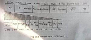
Frame Format of 802.11 – wireless network
The MAC layer frame consists of nine fields as shown in fig. 20.5 1.
Frame Control (FC): This is 2 byte field and defines the type of frame and some control information. This field contains several different These are listed in the table below:
| Field | Explanation |
| Version | The current version is 0. |
| Type | Specifies the type of information in the frame body 00- management, 01-control, and 10-data. |
| Subtype | It defines the subtype of each type. For control frame subtype fields are: 1011-RTS, 1100-CTS, 1101-ACK. |
| TO DS | Indicates frame is going to distributed system. |
| From DS | Indicates frame is coming from distributed system. |
| More Flag | If the value is 1, means more fragments. |
| Retry | If the value is 1, means retransmitted frame. |
| Power Mgt | If the value is 1, means station is in power management mode. |
| More Data | If the value is 1, means station has more data to send. |
| WEP | WEP stands for wired equivalent privacy; If set to 1 means encryption is implemented. |
| Rsvp | Reserved |
frame format for IEEE My Study Level
2. D. It stands for duration and is of 2 bytes. This field defines the duration for which the frame and its acknowledgement will occupy the channel. It is also used to set the value of NAV for other stations.
3. Addresses. There are 4 address fields of 6 bytes length. These fo addresses represents source, destination, source base station and destination base station.
4. Sequence Control (SC). This 2 byte field defines the sequence number frame to be used in flow control.
5. Frame body. This field can be between 0 and 2312 bytes. It contains the information.
6. FCS. This field is 4 bytes long and contains CRC-32 error detection sequence.
IEEE 802.11 Frame types – wireless network
There are three different types of frames:
1. Management frame
2. Control frame
3. Data frame
1. Management frame. These are used for initial communication between stations and access points.
2. Control frame. These are used for accessing the channel and acknowledging frames. The control frame are RTS and CTS.
3. Data frame. These are used for carrying data and control information. 20.1.5
802.11 Addressing – wireless network
⚫ There are four different addressing cases depending upon the value of To DS and from DS subfields of FC field.
⚫ Each flag can be 0 or 1, resulting in 4 different situations.
1. If To DS = 0 and From DS = 0, it indicates that frame is not going to distribution system and is not coming from a distribution system. The frame is going from one station in a BSS to another.
2. If To DS=0 and From DS = 1, it indicates that the frame is coming from a distribution system. The frame is coming from an AP and is going to station. The address 3 contains original sender of the frame (in another BSS).
3. If To DS = 1 and From DS = 0, it indicates that the frame is going to distribution system. The frame is going from a station to an AP. I address 3 field contains the final destination of the frame.
4. If to DS = 1 and from DS = 1, it indicates that frame is going from one AP to another ASP in wireless distributed system.
| TO DS | From DS | Address 1 | Address 2 | Address 3 | Address 4 |
| 0 | 0 | Destination | Source | BSS ID | N/A |
| 0 | 1 | Destination | Sending AP | Source | N/A |
| 1 | 0 | Receiving AP | Source | Destination | N/A |
| 1 | 1 | Receiving AP | Sending AP | Destination | Soruce |


Leave a Reply